3 Easy Facts About Wedge Barriers Described
Table of ContentsThe Ultimate Guide To Wedge BarriersAll About Wedge Barriers
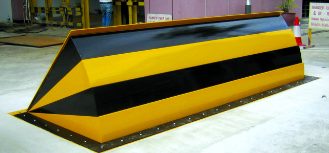
14 and the surface area 12 to which the barrier 10 is protected might be made from concrete - Wedge Barriers. 2, the barrier 10 is mounted to or includes an anchor or subframe (e. g., support 30 displayed in FIG. 2 )safeguarded under the surface 12. The bather 10 may be bolted to the support or secured to the anchor by various other mechanical bolts. In the illustrated personification, the obstacle 10 consists of a wedge plate 16, which includes a section that is considerably parallel with the surface 12 when the obstacle 10 is in the retracted placement. Simply put, vehicles or people might pass over the barrier 10 when the obstacle 10 is in the pulled back placement and experience small elevation about the surface 12 while on the barrier 10. As reviewed thoroughly listed below, when the obstacle 10 remains in the deployed setting, the wedge plate 16 is held and supported in an increased placement by a training device of the barrier 10. Furthermore, the parts 18 may be bolted or otherwise mechanically coupled to one an additional. In this way, fixing or replacement of several parts 18 may be simplified and streamlined. That is, repair work or substitute of solitary parts
18 might be done faster, quickly, and expense effectively. FIG. In specific embodiments, the anchor 30 may be a steel structure including plates, light beams(e. g., I-beams ), and/or other structures that are secured within the foundation 14, which may be concrete. At his comment is here the surface area 12, a top side 28 of the anchor 30 might go to the very least partly subjected
, consequently making it possible for the add-on of the barrier 10 to the anchor 30. g., threaded holes)in one or even more beams or plates of the anchor 30 may be subjected to the surface area 12. In this manner, screws 32 or various other mechanical fasteners might be made use of to secure the barrier 10 to the support 30. As the barrier 10 is mounted to the surface 12 of the foundation 14, collection of debris and various other material underneath the barrier may be reduced, and reference parts of the bather 10 might not be subjected to below quality settings. As suggested by recommendation numeral 52, the training device 50 consists of components got rid of under the wedge plate 16. The elements 52 beneath the wedge plate 16 might include an electromechanical actuator, a webcam, one or even more webcam surface areas, and so forth. In addition, the lifting system 50 consists of a spring setting up 54
The springtime pole 58 is coupled to a cam(e. g., web cam 80 revealed in FIG. 4) of the lifting device 50. The springs 60 disposed concerning the spring rod 58 are kept in compression by spring supports 62, consisting of a dealt with spring assistance 64. That is, the set spring assistance 64 is taken care of about the structure 14 et cetera of the bather 10.
An Unbiased View of Wedge Barriers
The continuing to be pressure applied to
the cam camera deploy release wedge plate 16 may be provided by an great site electromechanical actuator 84 or other actuator. The spring assembly 54 and the actuator 84(e. Wedge Barriers. g., electromechanical actuator)might run together to equate the cam and raise the wedge plate 16.
As mentioned above, in the deployed position, the wedge plate 16 offers to block accessibility or travel past the obstacle 10. The obstacle 10(e. g., the wedge plate 16 )might obstruct pedestrians or automobiles from accessing a home or path. If an automobile is taking a trip in the direction of the released wedge plate 16(e. For example, in one situation, the safety legs 86 may be expanded duringmaintenance of the barrier 10.